Similar
A system of instruction in X-ray methods and medical uses of light, hot-air, vibration and high-frequency currents - a pictorial system of teaching by clinical instruction plates with explanatory text (14570309768)
Summary
Identifier: systemofinstruct00mone (find matches)
Title: A system of instruction in X-ray methods and medical uses of light, hot-air, vibration and high-frequency currents : a pictorial system of teaching by clinical instruction plates with explanatory text : a series of photographic clinics in standard uses of scientific therapeutic apparatus for surgical and medical practitioners : prepared especially for the post-graduate home study of surgeons, general physicians, dentists, dermatologists and specialists in the treatment of chronic diseases, and sanitarium practice
Year: 1902 (1900s)
Authors: Monell, S. H. (Samuel Howard), d. 1918
Subjects: Vibration X-rays Diagnosis, Radioscopic Thermotherapy Electrotherapeutics X-Ray Therapy Vibration Diagnosis
Publisher: New York : E.R. Pelton
Contributing Library: Francis A. Countway Library of Medicine
Digitizing Sponsor: Open Knowledge Commons and Harvard Medical School
Text Appearing Before Image:
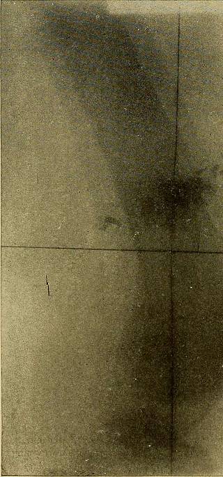
Plate 35.—Cross-wires for marking quadrants on negative. It is often useful to so markthe negative that it will show the central point of exposure with the field divided into fourright-angled parts. This Instruction Plate shows a plate in light-proof envelopes on a basewhich has two cross wires drawn tightly over at and intersecting in the middle. Focus thetube vertically over the point of intersection and freshly wet the cotton wrapping of the wireswith any ink that will mark the skin. Then. place the part on the plate and make theexposure. The marks of the wires will be imaged on the negative by the rays and printedon the skin by the ink. Thus the radiograph and part can be compared after the plate isdeveloped and any desired measurements may be made. This device is especially employed inmaking stereoscopic radiographs. It i.s well to laj a metallic letter R on the upper corner ofthe right-hand quadrant to identify it for all examinations.
Text Appearing After Image:
Plate 3G.-—This plate shows the markings on the negative of the cross wires ilhistrated inthe last figure which divide the picture into equal quadrants and assist in defining the exami-nation of the negative and print. Some operators use this form of landmark for all radio-graphs. EADIOGEAPHIC EXPOSING TECHNICS 117 it is proof that the object casting it was near the film, and per contra,if any shadow is enlarged and hazj on its borders, the tube distancein both cases being correct, it is proof that the object is at some in-terval from near contact with the film. These laws of definition areboth well illustrated in the frontispiece, the two circles being madeof the same steel wire. The contrast is more extreme than in anypart of the body, because the hazy circle was a greater distance abovethe film and nearer the tube than tissues are. Position of Patient for Radiograph.—Cases fall into two classes:those who can move freely and assume any desired position, and thosewho cannot. Hosp
Tags
Date
Source
Copyright info


